
Tensile Structure Installation: Step-by-Step Engineering Guide
Tensile structure installation is the on-site assembly and tensioning of a pre-engineered membrane-and-cable system onto its support frame, following a strict sequence from foundation work through final commissioning. A typical medium-sized project requires 12–14 weeks from design approval to handover, while the membrane itself can be deployed and tensioned in as little as 2–4 weeks depending on weather and site access.
But timelines tell only part of the story. The real risk in any tensile membrane project lies in the details that precede the first crane lift: patterning accuracy, seam strength, anchor bolt alignment, and the pretension specified by the engineer. Get one wrong, and the membrane will not find its designed shape. Worse, the field team will discover the problem when the fabric is already in the air.
In this guide, we walk through the complete tensile structure installation process. You will learn how each phase connects to the next, what standards govern safe execution, where costs concentrate, and which mistakes cause the most expensive rework. Whether you are a procurement manager evaluating a contractor’s proposal or a project engineer planning your next membrane roof, this article gives you the specification-level insight you need to protect your schedule and your budget. Partner with LY TRUSTLINK for your next membrane architecture project and benefit from our experience in creating lightweight, efficient, and visually distinctive tensile structures.
Key Takeaways
- Tensile structure installation follows six controlled phases: design, fabrication, foundation/frame work, membrane deployment, tensioning, and commissioning.
- Installation labor and equipment account for 15–25% of total project cost, with membranes deployable at rates up to 2,000 m² in five days under ideal conditions.
- Work stops when wind speeds exceed approximately 5 m/s; Glass-PTFE membranes require ambient temperatures above +5°C.
- ASCE 55-16, NFPA 701, ASTM E84, and IBC Chapter 31 provide the primary compliance framework for permanent tensile membrane structures.
- Most field failures trace back to fabrication or foundation errors, not the installation crew. Precision upstream prevents crisis downstream.
What Is Tensile Structure Installation?
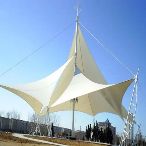
Tensile structure installation is the physical realization of a tension-based architectural system. In conventional construction, columns and beams carry compression and bending loads. A tensile structure transfers forces through a thin, flexible membrane held in tension by masts, arches, cables, and edge beams. The fabric has no structural capacity until it is stretched into its final, doubly curved geometry.
The process divides into three domains:
- Design and fabrication: form-finding, load analysis, patterning, cutting, and welding the membrane off-site.
- Substructure and hardware: foundations, anchor bolts, masts, arches, edge cables, and tensioning fittings.
- Membrane installation: unloading, unfolding, attaching, and progressively tensioning the fabric to its engineered prestress.
Because the membrane is manufactured to a compensated pattern, intentionally cut smaller than the final span, it can only achieve its design shape under the correct tension. That makes installation a precision operation, not a covering exercise. The crew executes a sequenced loading protocol that brings the fabric into equilibrium with the structure around it.
Ready to source installation-ready membrane for your next project? Request a custom membrane quote and our engineering team will review your patterning, seam, and tensioning requirements.
How Long Does Tensile Structure Installation Take?
Total tensile structure installation duration depends heavily on scale, complexity, and approval timelines. The actual on-site membrane work, however, is often the shortest phase.
| Project Scale | Total Duration (Design to Handover) | On-Site Membrane Installation |
|---|---|---|
| Small canopy or shade (< 500 m²) | 4–10 weeks | 3–7 days |
| Medium structure (500–2,000 m²) | 12–14 weeks | 2–4 weeks |
| Large roof or facade (> 4,000 m²) | 4–5+ months | 4–8 weeks |
| Steel-framed tensile building | 6–12 months | 2–4 weeks |
These figures assume parallel workflows: design and fabrication proceed while foundations cure. A specialized crew can install 2,000 m² of membrane in five working days once the frame and cables are in place. The constraint is rarely labor output. It is weather, access, and the need to tension the fabric in a single controlled sequence.
For steel-framed tensile buildings, Collinson Tensile reports that design and planning alone can consume 26–39 weeks when planning permission is included. Fabrication of the steel frame takes 10–16 weeks, and site preparation ranges from 4–26 weeks depending on civil works. The membrane installation remains the final, rapid phase.
The Tensile Structure Installation Process
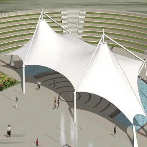
The installation process follows a logical chain. Each step creates the conditions for the next one. Skipping or rushing a step does not save time. It transfers risk to a later phase, where corrections cost exponentially more.
Phase 1: Pre-Installation Planning
Pre-installation planning begins long before the first delivery truck arrives. The project team reviews site surveys, environmental data, and the engineer’s form-finding model. They confirm coordinate systems match between fabrication drawings and site survey, anchor bolt locations are achievable, crane access routes accommodate mast heights and panel sizes, and temporary staging areas are available.
This is also when the contractor verifies that membrane panels were fabricated to the correct compensated pattern. A costly error is discovering in the field that a panel was cut to an earlier geometry revision. At that point, the only solutions are field seaming, rarely acceptable for appearance or strength, or remanufacturing.
Phase 2: Foundation and Site Preparation
Foundations for tensile structures resist tension, not just compression. Masts and arches pull upward and sideways as the membrane tries to collapse inward. The foundation system counters these reactions through mass, friction piles, tension piles, or ground anchors.
Typical foundation types include:
- Spread footings: used where soil bearing capacity is adequate and loads are moderate.
- Drilled or driven piles: used where uplift or lateral loads dominate.
- Grade beams: tie multiple footings together to distribute loads.
- Gravity anchors: massive concrete blocks resisting high pull-out forces, common in cable-net roofs.
Anchor bolts must be positioned within the tolerance specified by the engineer. Even a 20 mm misalignment at the base can translate into a significant error at the top of a 15 m mast. Concrete must reach design strength before any structural load is applied.
Phase 3: Structural Frame and Cable Installation
With foundations cured, the crew erects the primary support structure. Masts, arches, columns, and frames are lifted by crane and secured to anchor bolts. Secondary elements, purlins, struts, bale rings, and clamping plates, follow.
The cable network is then installed. Ridge cables connect high points, valley cables define low points and drainage paths, edge or catenary cables run along the membrane perimeter, back stays anchor masts against overturning, and wind suction cables resist uplift in exposed locations. All cables are laid out with terminations, turnbuckles, and rigging screws in place, left loose until the membrane is attached.
Phase 4: Membrane Deployment
During tensile membrane installation, membrane panels arrive folded or rolled, depending on material and size. The crew unloads them near the work area and inspects each panel for shipping damage, fabrication marks, and panel identity. For large roofs, individual membrane fields are often limited to 500 m² or less. Larger panels become difficult to handle and increase the risk of folds or kinks, especially with PTFE-coated glass fabrics.
Deployment proceeds methodically:
- Unfold the panel on a clean surface or directly over the frame.
- Orient the panel using alignment marks matched to the structure.
- Attach temporary restraint points to prevent wind movement.
- Connect the panel to edge cables, clamping plates, or mast rings at designated anchor points.
Safety nets and soft-soled footwear are mandatory. A single footstep on a folded PTFE panel at the wrong angle can create a permanent crease that weakens the fabric locally.
Phase 5: Progressive Tensioning
Tensioning is the most technically demanding phase of tensile structure installation. The crew applies prestress gradually, moving point to point in a sequence defined by the engineer. The goal is to bring the membrane into its designed shape without overloading any connection.
Common tensioning methods include:
- Turnbuckles and rigging screws: used at perimeter edges and cable ends.
- Hydraulic jacks: used at mast bases or high-point connections.
- Come-alongs and winches: used to pull corners or large panels into position.
- Cable shortening: achieved by adjusting swaged studs at membrane plates.
For hypar structures, high points are positioned before low points. This establishes the correct anticlastic curvature before final perimeter tension locks the geometry in place.
Control is monitored by measuring force at representative points and by checking displacement of force application points against the engineer’s targets. The accepted field standard allows wrinkles no greater than 250 mm in fewer than three locations per 750 m² of membrane surface.
Mini-Story: The Cost of a Patterning Error
When Marcus Chen’s team installed a 1,200 m² tensile canopy over a sports facility in Shenzhen, everything proceeded on schedule until the final tensioning pass. The crew could not eliminate a persistent diagonal wrinkle running across the central bay. Investigation traced the issue to a patterning revision that had not been transferred to one fabric panel. The panel was 180 mm too long in one direction. Because the membrane had already been lifted and partially tensioned, the only acceptable remedy was to remove it, ship it back for recutting, and reinstall a corrected panel. The delay added eleven days to a three-week installation and consumed the entire contingency budget.
Phase 6: Final Inspection and Commissioning
After full tensioning, the tensile structure installation process moves to inspection and handover. The checklist typically covers membrane tension uniformity, connection integrity at clamping plates and cables, drainage paths, electrical penetrations, membrane cleaning, and as-built documentation.
The owner receives operation and maintenance instructions, including inspection intervals. ASCE 55-16 requires annual inspections for safety conditions and biennial inspections by a professional engineer, registered architect, or manufacturer-certified individual for permanent membrane structures.
Visual Reference: Tensile Membrane Installation in Progress
The following time-lapse illustrates the staged deployment and tensioning of a tensile membrane structure from frame erection through final fabric tensioning.
Material-Specific Installation Considerations
Not all membranes behave the same way during tensile membrane installation. Each material demands specific handling protocols, and understanding these differences is essential for any tensile fabric structure installation project.
PVC-Coated Polyester
PVC tensile membrane installation most commonly uses PVC-coated polyester, the standard membrane for commercial canopies, parking shades, and temporary event structures. It is flexible, weldable by high-frequency (RF) welding, and tolerant of moderate folding. Crews can handle PVC panels in temperatures as low as 0°C, though colder conditions slow work and increase stiffness.
Key installation notes:
- Store panels out of direct sunlight before deployment to prevent surface temperatures from exceeding 60°C.
- Use clean gloves and footwear to avoid transferring oils or dirt to the coated surface.
- Verify that all RF-welded seams are intact before tensioning begins. A failed seam under load will propagate rapidly.
For cold-climate installations, cold-environment laminated fabrics retain pliability well below standard PVC limits.
PTFE-Coated Glass Fiber
PTFE-coated glass fiber is the premium choice for permanent architectural roofs. It offers 35–40+ year lifespan, high translucency, and self-cleaning surface properties. It is also far less forgiving during installation.
Glass-PTFE membranes must not be folded below their minimum bending radius. Kinks and creases are permanent and reduce load capacity. They require installation temperatures above +5°C; cold glass fibers become brittle and susceptible to fracture. They also demand clean, padded handling surfaces, since abrasion can damage the PTFE coating.
Because PTFE panels are stiffer and heavier than PVC, installation crews are larger and lifting equipment is more substantial. The reward is a roof that retains its appearance and structural performance for decades.
ETFE Cushions and Foils
ETFE (ethylene tetrafluoroethylene) is installed as thin foils, often in pneumatic cushion systems. ETFE foils are extremely lightweight and are typically tensioned into aluminum extrusion frames using a keder or rope-edge system.
Installation differences:
- Foils are pre-cut to precise dimensions and cannot be field-trimmed without specialized equipment.
- Cushion systems require air supply units, pressure sensors, and integration with the building management system.
- ETFE has high elongation, so tensioning must follow the manufacturer’s exact preload specification.
Safety, Standards, and Quality Control
Tensile structure installation operates at the intersection of structural engineering, fire safety, and building code compliance. The standards that govern tensile membrane installation define whether the structure can be permitted, insured, and maintained.
Primary Standards
- ASCE 55-16: Tensile Membrane Structures. Covers design, analysis, fabrication, and erection criteria for permanent and temporary membranes.
- NFPA 701: Standard Methods of Fire Tests for Flame Propagation of Textiles and Films. Mandatory for membrane materials in most jurisdictions.
- NFPA 102: Standard for Grandstands, Folding and Telescopic Seating, Tents, and Membrane Structures. Addresses life safety, fire protection, and emergency egress.
- ASTM E84: Standard Test Method for Surface Burning Characteristics of Building Materials. Class I membranes must show flame spread index ≤25 and smoke developed index ≤50.
- IBC Chapter 31: Governs special construction types, including permanent membrane structures.
Compliance documentation should be available before installation begins. A procurement manager should not accept a membrane shipment without the corresponding NFPA 701 Test 2 report and seam strength test data.
Weather Limits for Safe Installation
Weather is the single largest uncontrollable variable in tensile structure installation. The large, lightweight surface area of an unrestrained membrane acts like a sail. Most contractors suspend membrane work when wind speeds exceed 5 m/s. Rain creates slipping hazards and can trap moisture between folded panels. Extreme heat makes PVC panels soft and difficult to tension uniformly.
Temperature limits by material:
| Material | Minimum Installation Temperature | Primary Concern |
|---|---|---|
| PVC-coated polyester | 0°C | Increased stiffness, reduced weldability |
| PTFE-coated glass fiber | +5°C | Brittleness of glass fibers |
| ETFE foil | Per manufacturer | Thermal expansion affects preload |
Wrinkle, Patch, and Tension Tolerances
Quality control during tensioning relies on measurable tolerances:
- Wrinkles: ≤250 mm in fewer than three locations per 750 m² is commonly accepted.
- Patches: One small patch, typically 150 mm × 150 mm, per 750 m² may be acceptable if located away from high-stress zones.
- Tension: Verified by load cells at representative points or by measuring displacement of key nodes against the form-finding model.
Common Mistakes in Tensile Structure Installation and How to Avoid Them
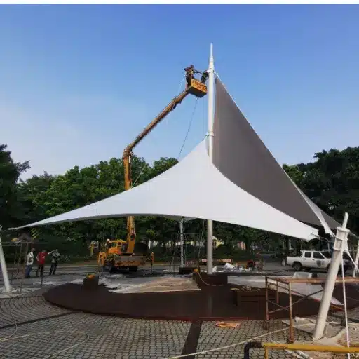
Even experienced contractors encounter problems during tensile structure installation. The difference between a manageable issue and a project crisis is usually whether the problem was anticipated. Understanding common mistakes in tensile structure installation before they occur is the best form of risk management.
Inadequate Site Analysis
Failing to assess wind exposure, solar orientation, and soil conditions leads to mismatched foundation designs and drainage problems. Complete a site-specific load study before finalizing the membrane pattern.
Foundation Misalignment
Anchor bolt tolerances are tight for a reason. Verify bolt positions against fabrication drawings before pouring concrete. Adjustments after curing are expensive and often compromise the connection.
Improper Tensioning
Over-tensioning tears fabric or overloads masts. Under-tensioning produces sagging, ponding, and wind flutter. Both result from ignoring the engineer’s tensioning sequence. Apply load gradually and monitor continuously.
Ignoring Drainage and Ponding
Water that cannot drain adds mass and stress. Ponding occurs when the membrane lacks sufficient curvature or pretension. Design adequate fall, locate drains at low points, and confirm water flow paths during inspection.
Unskilled Labor or Missing Supervision
Tensile membrane installation is a specialty trade. General construction crews rarely understand fabric behavior, cable rigging, or tension control. Require a manufacturer-certified supervisor or experienced tensile installer on site during critical phases.
Mini-Story: The Weather Window That Wasn’t
In 2024, a logistics operator in Rotterdam scheduled the membrane installation for a 3,500 m² truck canopy during what forecasters predicted would be a calm week. On day two, a low-pressure system brought sustained winds of 9 m/s. The crew had partially deployed a 900 m² PVC panel that could not be left unsecured overnight. Instead of forcing the work, the supervisor ordered the panel refolded and secured, then resequenced the remaining days around shorter weather windows. The decision added two days to the schedule but prevented the panel from contacting a steel edge and tearing. The operator later noted that the avoided rework would have cost more than the delay.
Tensile Structure Installation Cost Breakdown
The cost of installing a tensile structure is a significant line item in any tensile structure budget. Based on LY TRUSTLINK’s tensile structure cost guide, tensile membrane structure installation cost breakdown typically shows labor and equipment representing 15–25% of total project cost.
Total installed costs vary by material and complexity:
| Structure Type | Installed Cost Range |
|---|---|
| Basic PVC installation | 150–150–400/m² |
| Mid-range PVC/PVDF | 110–110–330/m² |
| Premium PTFE | 30–50% above PVC |
| High-end architectural | Up to $1,500/m² |
Factors that increase installation cost include:
- Complex geometry: hypar and conical forms require more labor and generate higher fabric waste.
- Site access constraints: congested urban sites or high elevations require specialized cranes and lifts.
- Foundation difficulty: poor soil or deep piles extend civil works.
- Weather delays: each day of crane rental and crew standby adds cost.
- Material handling requirements: PTFE and ETFE demand more care and larger crews than PVC.
A well-documented fabrication package reduces field questions and change orders during tensile membrane construction, allowing the installation contractor to bid more confidently and execute more efficiently.
Need a precise cost estimate for your tensile membrane project? Review our tensile structure cost guide for a complete breakdown by project phase and material.
Conclusion
Tensile structure installation is the final, visible phase of a process that begins with form-finding and ends with a precisely tensioned architectural surface. The installation itself is rarely the longest stage, but it is where every upstream decision becomes visible. A patterning error, a misaligned anchor bolt, or an ignored weather window will reveal itself when the fabric is pulled tight.
The most successful projects share three traits:
- Fabrication precision: membranes cut, welded, and inspected to the final design geometry.
- Foundation accuracy: anchor points placed within tolerance and cured to strength.
- Controlled execution: tensioning performed by specialists following the engineer’s sequence.
LY TRUSTLINK manufactures high-tenacity polyester base fabrics and PVC-coated membranes engineered for tensile applications. We support our partners with patterning consultation, seam strength documentation, and material specifications that make installation smoother from the first lift to the final bolt.
Ready to make your next tensile structure installation predictable? Talk to an engineer about your project requirements, lead times, and compliance documentation.
Sources and Further Reading