
Tensile Structure Design: Engineer’s Guide to Form-Finding & Analysis
Tensile structure design is the engineering discipline of shaping membrane fabrics so they remain in tension under every load case, creating stable shelter with minimal material. Unlike conventional buildings that resist gravity through compression and bending, tensile structures derive strength from carefully controlled pull forces in the membrane, boundary cables, and masts.
That visual lightness is what makes tensile architecture appealing. It is also what makes the design process unforgiving. In a steel-framed building, the architect can adjust a roofline without necessarily changing structural behavior. In tensile structure design, the shape is the structure. Change the curvature and you change the stress path, drainage, wind response, and fabric quantity.
This guide walks through the complete tensile structure design workflow, from concept to installation, with the specifications and standards procurement and engineering teams need. By adhering to rigorous industry standards, our solutions provide unparalleled reliability and efficiency for enterprise-level applications. You will learn how form-finding, load analysis, material selection, patterning, and fabrication sequencing interact, and where projects most often fail. Every tensile structure presents unique challenges. Reach out to LY TRUSTLINK for expert guidance on material selection, structural optimization, and project feasibility.
Key Takeaways
- Tensile structure design is a seven-phase workflow in which form-finding, analysis, patterning, and installation continuously influence one another.
- Double curvature (anticlastic form) is mandatory for stability; flat or single-curved membranes will pond water, flutter in wind, and concentrate stress.
- Material selection should match project lifespan and load cases: PVC-coated polyester for cost-effective spans, PTFE-coated fiberglass for permanent landmarks, ETFE for translucency.
- Patterning compensates for fabric stretch during tensioning; panels are deliberately cut smaller than the final 3D shape so they reach the design prestress on site.
- Most failures originate at connection details, foundations, or from underestimated wind loads, not in the membrane itself.
What Tensile Structure Design Really Means
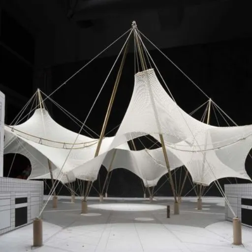
Tensile structure design is the process of defining a membrane geometry, support system, and material specification that keeps a fabric skin in biaxial tension under all expected conditions. The membrane carries load by redirecting forces through its surface to boundary cables, masts, arches, and foundations.
The central principle is simple: the fabric cannot go slack or experience compression. If any region loses tension, it will wrinkle, collect water, or flutter. If the curvature is wrong, wind uplift can amplify rather than dissipate. This is why tensile structure design is as much about geometry as material strength.
Compared with conventional construction, tensile structures use far less material to cover comparable spans. A stadium roof that would require hundreds of tons of steel decking can be achieved with a membrane weighing grams per square meter plus a cable network. The trade-off is precision: every dimension, seam direction, and tensioning sequence must be calculated before fabrication begins.
The Four Forces That Govern Every Design
Every tensile structure balances four force categories:
- Membrane prestress — the baseline tension applied in both warp and weft directions to keep the surface taut.
- Boundary cable tension — the pull carried by edge ropes or catenary cables that define the membrane perimeter.
- Support reactions — the compression in masts or arches and the tension transferred to foundations.
- External loads — wind, snow, rain, seismic action, and temperature effects.
A successful design keeps the membrane in tension under every combination of these forces. That requirement shapes every decision that follows.
The 7-Phase Tensile Structure Design Process
The tensile structure design process is rarely linear. Each phase feeds back into the others, and changes in one area often require revisions elsewhere. The workflow can be organized into seven stages:
- Conceptual design and site analysis — define function, span, clearance, aesthetics, and environmental exposure.
- Form-finding — determine the equilibrium shape under prestress and boundary constraints.
- Structural analysis and load verification — apply code-required load combinations and check stress, displacement, and stability.
- Material selection — choose the membrane, topcoat, fire rating, and structural components.
- Patterning and compensation — flatten the 3D surface into 2D cutting patterns that account for stretch.
- Fabrication planning — specify seam layout, welding method, hardware, and prefabrication sequence.
- Installation sequencing and tensioning — erect supports, attach the membrane, and apply tension in a controlled order.
These phases loop back on themselves. A patterning decision may reveal that the chosen prestress is impractical. An installation constraint may force a change in seam direction. A supplier’s roll width may influence how panels are divided. Experienced designers iterate early so that surprises do not appear on site.
When the design team for a 28-meter airport canopy in Belgrade reached the patterning stage, they discovered that the planned panel orientation would have left seams running across the primary drainage path. Revisiting form-finding with seam constraints in mind produced a hyperbolic shape with a central drainage opening, and a roof that has performed without ponding for more than five years.
Form-Finding: Why Shape Cannot Be Arbitrary
Form-finding is the defining task of tensile structure design. It is the process of identifying a geometry that is in static equilibrium under a given set of prestress values and boundary conditions. You cannot simply draw a curved roof and ask an engineer to make it stand. The shape must find itself.
The reason is structural. A membrane has negligible bending stiffness. It can only resist load when it is already in tension and when the tension is oriented to oppose the applied force. The correct shape automatically channels forces toward the supports.
Why Double Curvature Matters
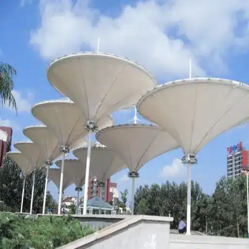
Stable tensile membranes are anticlastic: they curve in opposite directions along two perpendicular axes, like a saddle. This double curvature gives the surface stiffness against point loads and prevents ponding.
A synclastic shape curves the same way in both directions, like a dome. Without internal pressure, it is unstable under concentrated loads. A flat or single-curvature sheet is even worse, because it will sag, flap, and fail under snow or wind.
Engineering rules of thumb help control curvature:
- Chord-to-sag ratio: keep c/f ≤ 20 to ensure sufficient curvature.
- Boundary cable sag: target 8–10% of the span for a smooth catenary.
- Minimum prestress: typically 1.0 kN/m in both warp and weft for standard PVC membranes.
Form-Finding Methods Engineers Use
| Method | Best For | Software Examples |
|---|---|---|
| Force Density Method | Cable nets and early geometry | Easy, custom scripts |
| Dynamic Relaxation | Complex free-form surfaces | Kangaroo in Grasshopper |
| Updated Reference Strategy | Integrated FEA workflows | RFEM 6 with RF-FORM-FINDING |
| Transient Stiffness Method | Detailed non-linear analysis | SOFiSTiK, ANSYS |
Physical models still have value. Soap films form minimal surfaces, and scaled fabric models can verify that a digital shape will tension evenly. For most commercial projects, however, computational form-finding is faster and easier to integrate with structural analysis.
Request a consultation with LY TRUSTLINK today to discover how our custom tensile structure solutions can enhance your space while reducing long-term maintenance and construction costs.
Structural Analysis and Load Considerations
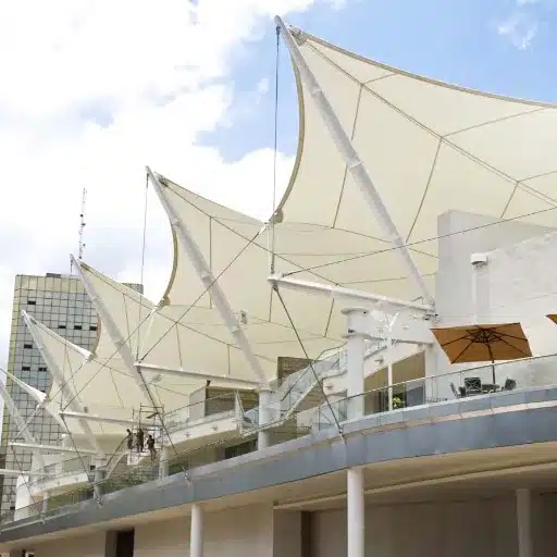
Once a form-found shape exists, the engineer applies load combinations from the relevant building code. Because tensile structures undergo large deformations before reaching equilibrium, linear analysis is usually not enough; geometric non-linearity must be included.
Critical Load Cases
- Dead load: self-weight of membrane, cables, hardware, and permanent fixtures.
- Live load: maintenance personnel and equipment, often specified as a minimum pressure by code.
- Wind load: frequently the governing load; uplift suction can be more severe than downward pressure.
- Snow load: must be evaluated for ponding, especially in low-curvature regions.
- Seismic load: relevant where the supporting structure is massive or the site is seismically active.
- Temperature effects: expansion and contraction alter prestress and edge geometry.
For large or unusually shaped structures, wind tunnel testing provides pressure coefficients that software cannot reliably predict. The European Design Guide for Surface Tensile Structures and the JRC outlook on Eurocode guidance for tensile membrane structures both emphasize that wind load characterization is one of the most consequential steps in the design process.
Material Modeling and Biaxial Testing
A common beginner mistake is to treat the membrane as an isotropic material. Woven fabrics have different stiffness in the warp and weft directions, the coating adds its own behavior, and the response changes with load ratio and duration.
Biaxial testing measures fabric stiffness under simultaneous tension in two directions. The resulting data feeds into the structural model and determines compensation values for patterning. Without biaxial data, stress predictions and final geometry are guesses.
For procurement teams, this is where supplier capability matters. A membrane manufacturer should provide mill certificates with tensile strength, tear resistance, adhesion and, for critical projects, biaxial test results. Architectural membrane fabric from a vertically integrated producer gives you traceability from yarn lot to finished roll.
Material Selection for Tensile Membranes
Material choice in tensile structure design balances lifespan, fire performance, translucency, cost, and maintenance. The four primary membrane types are:
- PVC-coated polyester: the workhorse for canopies, stadium roofs, and transit shelters. Cost-effective, flexible, field-repairable, available in many colors.
- PTFE-coated fiberglass: premium permanent material with 25–35+ year lifespan and Class A fire performance. Self-cleaning but higher cost.
- ETFE foil: lightweight, highly translucent, used in air-supported cushions and modern facades.
- Silicone-coated glass fiber: specialty applications requiring high temperature resistance or specific optical properties.
PVC Membrane Specification Ranges
For most commercial and infrastructure projects, PVC-coated polyester is the practical starting point. Specification ranges typically follow the load and span:
| GSM | Base Fabric | Tensile Strength | Best Application |
|---|---|---|---|
| 650–750 | 1000D polyester | 2,500–3,500 N/5cm | Small canopies, awnings, walkway covers |
| 850–950 | 1000D × 1300D | 4,000–4,500 N/5cm | Parking canopies, transit stations, courtyards |
| 1050–1250 | 1300D–1500D | 5,500–6,300 N/5cm | Stadium roofs, arenas, exhibition halls |
| 1350–1800 | 1500D+ | 7,000+ N/5cm | Industrial warehouses, extreme climates |
These values are representative. Final selection depends on local wind and snow loads, desired design life, and fire classification. Testing to EN ISO 1421 for tensile strength and EN ISO 2411 for coating adhesion provides the documentation engineers need.
Topcoat, Fire, and Compliance Choices
The topcoat determines how long a PVC membrane will resist UV, dirt, and chemical exposure:
- Acrylic lacquer: economical, 10–15 year service life in moderate climates.
- PVDF topcoat: superior UV resistance and self-cleaning, 15–25+ year service life.
- TiO₂-reinforced formulations: enhanced reflectivity and longevity in harsh sun.
Fire performance must be specified by standard, not by vague claims. Common requirements include NFPA 701 for the U.S. market, EN 13501-1 B1 or DIN 4102 B1 for Europe, and M2 for France. If your project crosses borders, confirm which certification the authority having jurisdiction will accept.
When non-standard weights, widths, or coatings are required, custom membrane specifications from an OEM-capable manufacturer keep the project on schedule. Prototype samples for weld testing and certification should be available before bulk production begins.
Patterning and Compensation: From 3D Form to 2D Fabric
Patterning is the step that translates the three-dimensional, form-found surface into flat pieces that can be cut from rolls and reassembled. It is unique to membrane construction and demands precision.
The process involves:
- Dividing the surface into panels that respect roll widths and seam locations.
- Flattening each panel from 3D to 2D while minimizing distortion.
- Applying compensation — reducing dimensions to account for the stretch that occurs during tensioning.
- Aligning the warp direction with the principal stress path for structural efficiency.
Compensation is the subtlest part. Fabric stretches when tensioned. If panels were cut to the final 3D dimensions, the installed membrane would be larger than intended and prestress too low. Patterning software therefore outputs slightly smaller panels, so the structure reaches its design shape and tension after installation.
The amount of compensation depends on the fabric, load direction, and intended prestress. It is derived from biaxial test data and validated through trial tensioning when necessary.
Common Tensile Structure Design Mistakes
Most failures in tensile architecture do not begin in the fabric. They begin in decisions made before fabrication. Here are the most common errors:
- Ignoring site-specific wind and climate loads. Generic wind pressures are not enough for large or irregular forms.
- Forcing a shape without proper form-finding. A visually striking curve that is not in equilibrium will wrinkle and overload local connection points.
- Selecting material based on cost alone. A lower-spec membrane may save on fabric but increase structural hardware, maintenance, and replacement costs.
- Weak connection detailing. The highest stress concentrations occur at edges, corners, and cable attachments.
- Improper tensioning during installation. Over-tensioning tears fabric; under-tensioning causes sagging and flutter.
- Inadequate foundation design. Tensile structures generate large uplift and horizontal reactions.
- Poor drainage and curvature. Low spots become ponds, and ponds become structural failures under snow.
- Overcomplicating geometry. Every additional peak and valley increases fabrication risk and cost.
- Neglecting maintenance access. Even the best membrane needs inspection, cleaning, and retensioning.
- Inaccurate field measurements. Small errors in anchor bolt placement become large errors in membrane fit.
A procurement manager we worked with inherited a canopy project where the original designer had specified a 650 gsm PVC membrane for a 35-meter span in a high-snow region. The fabric was technically within its tensile strength rating, but the long-term creep and deflection under snow load were never modeled. Within two winters, the membrane had sagged enough to trap meltwater. The remediation, a heavier membrane with revised curvature and new edge cables, cost more than specifying correctly the first time.
Tensile Structure Design Software Comparison
Specialized software is essential because standard frame-analysis programs do not handle form-finding or large-displacement membrane behavior. The right tool depends on project stage and team expertise.
| Software | Primary Use | Best For | Notes |
|---|---|---|---|
| RFEM 6 + RF-FORM-FINDING | Integrated FEA and form-finding | Professional engineering offices | RWIND 2 provides CFD wind analysis |
| Rhino + Grasshopper + Kangaroo | Parametric form-finding | Architects and early-stage designers | Free plugin, visual scripting environment |
| MPanel | Patterning and analysis | Fabricators and pattern makers | Industry-standard patterning output |
| Easy | Specialized tensile analysis | European consultants | Form-finding, load analysis, patterning |
| WinFabric | Patterning and nesting | Production shops | Cutting pattern generation and optimization |
| SOFiSTiK | Bridge and special structures | Large infrastructure projects | Advanced non-linear analysis capabilities |
For a deeper look at the RFEM workflow, the Dlubal tensile membrane structure design webinar demonstrates cable modeling, form-finding, static analysis, and wind load simulation in a single integrated environment.
Sustainability and Lifecycle Considerations
Tensile structures offer inherent sustainability advantages through material efficiency. A membrane roof uses a fraction of the material required by a conventional metal deck, reducing embodied carbon in the envelope. The lightweight structure also reduces foundation size and transportation emissions.
Operational benefits include natural daylighting. Translucent white PVC and ETFE reduce artificial lighting demand during daytime hours, and reflective topcoats can lower cooling loads in hot climates.
End-of-life options for PVC membranes have improved. Manufacturers such as Sioen Tensile Architecture operate chemical and mechanical recycling pathways that separate polyester from PVC and reprocess both into new products. Design for disassembly, using bolted connections rather than welded tabs for example, makes future recycling easier.
The main limitation is thermal performance. Single-layer membranes are poor insulators, best suited to applications where thermal resistance is secondary: canopies, atria, sports facilities, and covered walkways. Enclosed, conditioned spaces may require additional insulation layers or hybrid construction.
When to Engage a Membrane Manufacturer Early
Bringing a membrane manufacturer into the design process early reduces risk in several areas:
- Material selection and biaxial data — confirm the proposed fabric exists with the required properties and certifications.
- Custom widths and roll optimization — minimize waste by matching panel layout to available roll widths.
- Prototype samples — produce welded samples for pull testing, fire testing, and visual approval.
- Lead time planning — membrane fabrication is on the critical path for most tensile projects.
- Certification documentation — obtain test reports and compliance certificates the engineer of record and building official will require.
A manufacturer that understands tensile structure design acts as an extension of the project team, not a late-stage supplier. At LY TRUSTLINK, our engineering team supports projects from concept through certified delivery, with custom weights, coatings, widths, and fire-retardant formulations manufactured in-house.
Ready to move from concept to specification? Request a membrane specification review and receive a tailored recommendation for your span, climate, and compliance requirements.
Conclusion
Tensile structure design is a loop, not a checklist. Form-finding defines the geometry; structural analysis validates it; patterning prepares it for fabrication; and installation proves whether the design assumptions were correct. Each phase feeds back into the others, and the best projects account for those feedback loops from the start.
The difference between a successful tensile membrane and a problematic one usually comes down to three things: sufficient double curvature, accurate load analysis, and a membrane specification that matches the project’s real environmental demands. Get those right, and tensile architecture delivers spans, daylight, and visual impact that conventional construction cannot match.
If you are evaluating membrane options for a canopy, stadium roof, or architectural facade, start with the data. Review the fabric specifications, confirm the relevant fire and structural standards, and involve your membrane partner before the design is frozen. The right specification, validated early, is the foundation of a structure you can trust.
Talk to an engineer about your tensile project. Our team can review your drawings, recommend a membrane specification, and provide prototype samples for testing.
Sources and Further Reading
- TensiNet European Design Guide for Surface Tensile Structures
- JRC Technical Report: Prospect for European Guidance for Structural Design of Tensile Membrane Structures
- Dlubal RFEM 6 Tensile Membrane Structure Design Video
- Sioen Tensile Architecture: End-of-Life and Recycling
- Structurflex: Tensile Structure Applications